Manufacturers are constantly changing protection methodologies found in low-voltage power, insulated-case, and molded-case circuit breakers. Some of these changes are in response to new requirements such as NFPA 70, NFPA 70E, UL, and other standards. Other changes are simply improved methods to help a manufacturer garner a larger market share.
Before discussing testing and certification techniques for low-voltage circuit breakers (Part II of this story), here is an overview of some common types–and some misconceptions.
I2t/I4t Response Type
By default, digital electronic devices have an on/off nature. For example in a low-voltage breaker trip unit, when a short time set point is reached, the trip unit goes into pickup, and the timing circuit starts the countdown to the trip time based on the short time delay setting. The result is a very discrete and square time-current curve across all protective functions.
In setting a system with multiples of such digital devices, the task is fairly straight forward because all of the characteristic curves will have the same discrete shape and relatively narrow tolerance bands.
If, however, a protective device or power system component is present which has another characteristic curve shape, such as a thermal magnetic trip device with a smoother profile, the challenge is increased and requires “fitting” a discrete digital device to an analog device curve. This hurdle has been met by most if not all major manufacturers of low-voltage trip units by providing an option for inserting an algorithm into the long-time, short-time, and ground-fault protective functions to “shape” the time current characteristic curve to more closely match an analog device or piece of equipment.
Zone Selective Interlocking Type
This device class minimizes trip time in order to protect personnel and equipment on circuit breakers that do not have instantaneous trip functionality. Zone interlocking is designed to segregate an electrical system into zones, and through use of hard-wired communication between low-voltage breakers, ensure that the breaker responsible for that zone of protection is the device used to interrupt a fault. With the added information available to the system, circuit breaker tripping times can be reduced without fear of a nuisance trip, which can result in de-energizing more of the system than necessary.

Thermal Memory (aka Thermal Imaging) Types
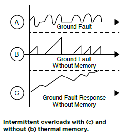
This method protects distribution system components from damage due to repeated intermittent overload events and periodic ground fault events. Advanced thermal memory functionality requires more accurate input parameters, resulting in a more accurate algorithm to model the thermal condition of conductors. The trip unit goes into pickup and begins timing as soon as the sensed current exceeds the long-time pickup value. When the sensed current drops below the pickup value, the timing circuit stops the timeout. If the current increases again above the pickup value in a short period of time, the trip unit starts its timeout to trip again, but doesn’t “remember” the previous overload and heating. With thermal memory, the circuit remembers a series of brief overloads that do not reach the timeout setting, so their cumulative effect will not cause overall damage to circuit components without tripping the circuit breaker.
Thermal memory allows a digital electronic trip unit to mimic the performance of a thermal magnetic circuit breaker. Only an electronic trip unit needs to be “taught to remember” what conditions the circuit was recently subjected to. Attempts have been made to improve the algorithm through the use of more accurate input parameters to allow use of the thermal memory function without nuisance trips.
Reduced Energy Let-Through (aka Quick-Trip, Arc Flash Reduction Maintenance System, Dynamic Arc Flash Reduction System, Alternate Maintenance Setting) Type
These systems reduce arc-flash severity that a worker downstream may be exposed to because of a fault. The four major factors contributing to the severity of an arc flash are:
- Fault current level
- Fault clearing time for the upstream protective device
- Distance from the fault to a subject worker
- Physical characteristics of the equipment subjected to the arc flash
By adjusting the time delay to trip and overcurrent pickup set points, the system limits the time an arc flash event persists. These setting changes are applied temporarily while personnel are working on an energized system downstream of the circuit breaker.
Instantaneous Fault Discrimination (aka Making Current Release) Type
This type increases personnel protection by enabling an instantaneous trip when a breaker is closed on a faulted circuit. Manufacturers can apply an instantaneous trip feature immediately after closing, on the order of 12x-25x the circuit breaker plug rating, to open with no intended delay. The making current release functionality is active for only a short preset time after the circuit breaker is closed.
The microprocessor based trip units described above allow protection options for undervoltage, overvoltage, current and voltage imbalances, underfrequency, overfrequency, and reverse power. Additionally there are alarms, indications, and diagnostics available to aid trouble shooting.
Part II of this story, which will appear in the next issue of BreakerBuzz, will look at testing, certification and commissioning approaches for the different types of low-voltage circuit breakers covered in this article.
www.westernelectricalservices.com, Vancouver, Wash. | Ph: 888-395-2021
Myriad features and capabilities dictate nuanced testing regimes | By Dan Hook, Executive Vice President, Western Electrical Services, Inc.
